Callisto RS232 to RS422 Line driver
RS232 to RS422 line driver
by Blair Dec 2021
Most Callisto radio installations have the receiver(s) along side the computer and are connected via a short RS232 cable, either via a usb to RS232 adapter or via a native RS232 serial port on the computer.
Our installation at Sunnydale in South Australia has the Callisto receivers located some 20 metres away from the computer and this distance is outside of the distance specification for the transmission of RS232 data, particularly at the data rate of 115200 baud which is used by the receivers for communication and data transfer.
While communications might and are possible over this distance, it does become a little ‘flaky’ with corrupted data packets sometimes arriving. These corrupted packets cause data sync problems, with the end result being that the computer gets the data packet with respect to a frequency out of sync and the whole data set gets moved from the start frequency.
There is no ‘resync’ , hardware handshaking or ‘next packet’ command sent, so this out of sync condition stays this way until a new ‘start’ command is sent, which may be the next day. Effectively corrupting the whole day’s data.
A possible solution was to use Ethernet to serial adapters such as the 4 channel USR-N540 available from IOT Store in Perth, and while these work very well at low data rates (I use one with my Radio Telescope), when I installed one of these at Sunnydale, there were still the occasional dropped packets at the continuous 115200 baud rate for 3 channels data which messed up the data.
The solution was to convert the RS232 protocol signals to RS422 or RS485 (multidrop) protocols which are designed to transmit data many 100’s of metres using current driven differential balanced lines.
Adding to the complication is the almost zero wait time between commands being sent from the computer and data being sent from the receivers, which I found was too short to allow the simple self powered RS232 to RS485 simplex devices (available on eBay for $10) enough time to ‘change directions’.
It quickly became apparent that a full duplex bidirectional RS232 to RS422 system would be required. A commercial solution is in the $100's for each end per channel and ended up being prohibitively expensive.
We currently have 3 receivers at Sunnydale, and the plan is to add a fourth, so I decided to make a dual channel RS232 to RS422 printed circuit board and put 2 boards in a box at each end to hopefully solve our current communications issues.
A Google search revealed some 'all in one' RS232 to RS422 converter chips, however, these were relatively expensive and difficult to obtain, so I went down the more common path of converting the computer's RS232 signal to TTL and then convert the TTL signal to RS422.
At the ‘far end’ I would need to receive the RS422 signal, convert to TTL and then convert the TTL back to RS232.
Different sex connectors are required at each end to connect from the computer (9 pin sub D female) and to connect to the receiver (9 pin sub D male) and as we already have three cat 5 Ethernet cables between the container where the computer is and the receiver box, using Rj11 connectors on the boards would enable me to use those cables without modification.
The board layout either needed to be configurable for each end or I would need 2 different boards, one at the computer end and one at the receiver end.
The design ended up with 14 jumpers to allow for the different configurations for each end. One evening was spent doing the board layout.
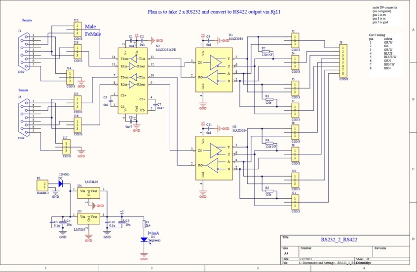
The result was a board that I could configure to be at either end and the signals are sent down the existing cat5 cables, using 2 pairs of a cat5 cable for 1 receiver. This way, 2 cat5 cables would be required for 4 receivers and only 1 board layout.
I sent the board design files off to JLCPCB (who I've never used before for manufacture) and received the bare pcb’s 10 days later for a grand cost of $23, most of that being for freight.
I'm impressed with the service from JLCPCB and the process to send the design files to them was fairly painless.
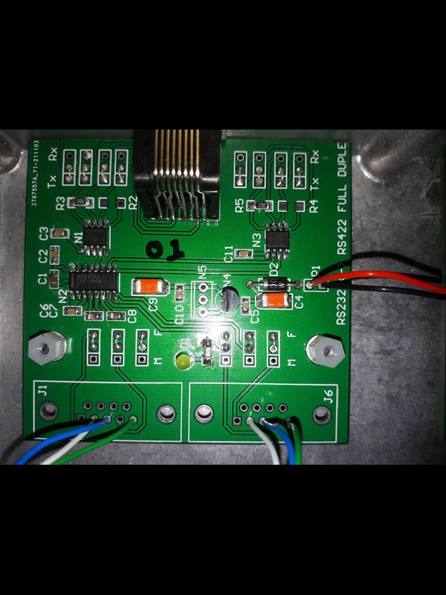
A 'loaded' board, you can see the jumper links, this board is configured to be at the PC end
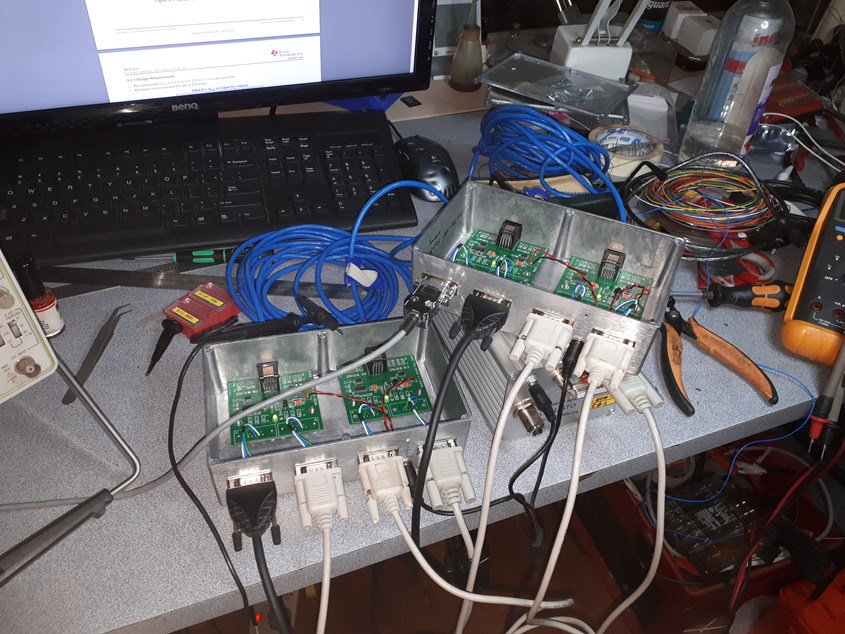
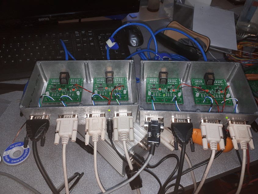
4 channels ‘daisy chained’ with both ends being tested on the bench, running 1 receiver through all the circuits, seems to work a treat!
I ran this setup for 4 days and didn't have any errors. While this isn't quite the distance that we have at Sunnydale, all the ins and outs work fine and the extra 20m distance shouldn't be an issue.
Just need to put on the lids and install them at Sunnydale.
These were installed at Sunnydale at our radio astronomy site and have performed flawlessly since installation.