Callisto Radio Spectrometer
Solar Radio Spectrometer
most recent update, 2nd Nov 2023
http://www.e-callisto.org/
“The CALLISTO spectrometer is a programmable heterodyne receiver built in the framework of IHY2007 and ISWI by former Radio and Plasma Physics Group (PI Christian Monstein) at ETH Zurich, Switzerland. The main applications are observation of solar radio bursts and rfi-monitoring for astronomical science, education and outreach. The instrument natively operates between 45 and 870 MHz using a modern, commercially available broadband cable-TV tuner CD1316 having a frequency resolution of 62.5 KHz. The data obtained from CALLISTO are FIT-files with up to 400 frequencies per sweep.”
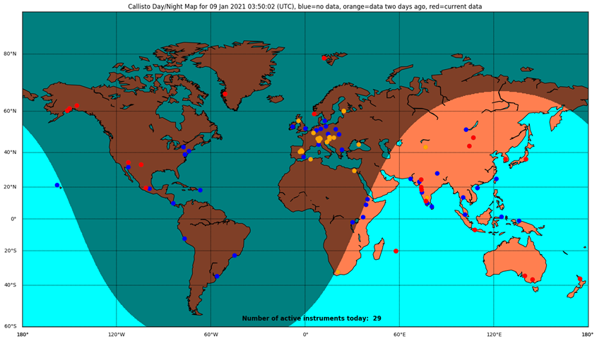
The above map shows the locations of the receivers within the e-Callisto network. Note the little red dot in South Australia, that's us!.
2nd Nov 2023
Peter and I made a visit to our radio site today to make some changes to the solar power systems (again).
We've had some issues over the past couple of years with some data getting slightly messed up, and I had some suspicions that it might be related to batteries / power supplies.
Last visit I installed a voltage data logger made up of an ADM 4280 -C data acquisition module that communicates via Modbus (a form of RS422).
These modules are about $40 on Alibaba and given the success that I had had with a data acquisition system (DAQ) I installed at our TPSO Seismic vault to monitor temperature and humidity and to control the humidity there, It seemed that this addition to our radio site might allow us to monitor the batteries, the performance of the 3 separate solar power systems and maybe track down any power related issues we might have at the radio site.
All 3 solar / battery systems have the same solar panels, lead acid gell cells, however the charging systems are different.
The one at the tower and our system in the container have Victron MPPT 75/15 chargers and these we are pretty happy with.
The 3rd system in the container had a Jaycar MPPT charger (it was purchased locally) and while it seems to work, when we upgraded the solar panels a couple of months ago, we started to see more data sync issues.
The installation of the ADM4280 module was in part to try and track down the issue and a good thing to have to actually monitor the battery systems anyway.. I wrote some python code to talk 'Modbus' to the ADM module runing on a Rasberry Pi4 and modified the ADM4280 from current mode to voltage mode. I did a bench test with my Fluke voltage calibrator to get a proper calibration for each channel and the voltages reported are to 3 decimal places and accurate to a millivolt! Perfect (overkill?) for our needs.
I initially ran the data acquisition module at 1 sample every minute , and managed to capture a 16.8 volt spike on the output of the Jaycar MPPT controller. Progress! It seems that the Jaycar MPPT charger might not be ideal for our usage..
I changed to python code to run at 1 sample per second for a few hours each morning (I could run it that way 24 hours a day), but it generates a few Mb each day and storage might become an issue.
We captured several voltage spikes during the next month and they seem to be related to when the Jaycar MPPT charger was in 'Bulk' charge phase (early in the morning) and when there were clouds passing the site. We suspect the averaging loop for the MPPT cycle in boost mode is done over a too long a period and when the Sun pops out from behind a cloud, the charger takes too long to respond and hence, we get the voltage spikes , they only last for a few seconds, but that's enough to mess with some of the data.
So, armed with data, Peter and I decided to replace the Jaycar MPPT with another Victron 75/15.
Our visit today was to install the new Victron and also to rewire the other power supply and install a fuse board on that system, (it had 'grown' somewhat as things kept getting added and was looking very untidy).
We also changed some of the loads from the container power supply system to our other system, hopefully balancing the battery capacity and loads some what.
We updated the firmware in all the Victrons to the latest and checked that all the settings were the same on each charger.
Overall, a fairly long day but rewarding day.
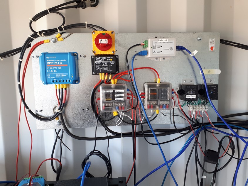
Here's a picture of the new Victron Charger (blue box upper left) installed on the container power system, it runs the communications to the real world.
It still needs more tidying up, I'll get some slotted box conduit some time and 'hide' all the cabling.
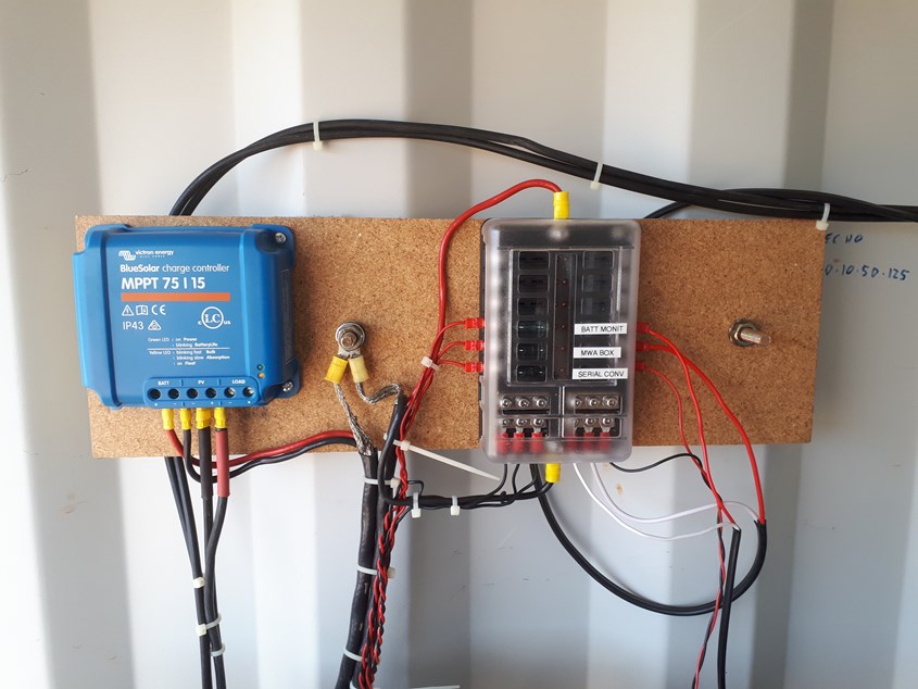
Here's the revamped and tidied up power system that runs our 5 Raspberry Pi's and receivers in the container.
We haven't used the 'LOAD' outputs on the Victrons, preferring to run everything from the batteries, hopefully to lower the power supply impedance and variations in doing so.
Initial data from the DAQ suggests that the charger change is worthwhile and the loads are more evenly distributed across the battery systems within the container.
As far as the Callisto system is concerned, it has been running well and picks up lots of outbursts from the Sun.
As we get closer to solar maximum, we aim to have our systems as reliable as possible and today's effort will certainly move forward in respect to that aim.
13th June 2023
Around March 2022, I contacted the Project Officer from Murchison Wide Field Array that is led by Curtin University and asked if it was possible to obtain several of their low noise preAmps from their array, a bit cheeky I guess but since they were building many 1,000's of them I hoped there might be a slim chance to obtain a couple.
I explained what we had done using the HF antenna design and a low noise front end that I had designed (based on the design they were using) and that we wanted to expand our capability and would like to use the VHF antenna , who's design was published on the web, but the design for the low noise amplifiers they were using was not available , and given the small size, would be difficult to replicate.
The then Project Officer, Mia, emailed me back and said Sure, I'll send you a couple, and 2 months later, 3 turned up.
I emailed her back thanking her and asked if there was any chance of the electronic circuit and she assisted there as well.
We are truly thankful for the assistance and parts we received as without them, the following could not have taken place.
Peter had wanted to upgrade the VHF antennae and receivers for some time as the large VHF LPDA was really not performing as we'd of liked.
Sure, it does occasionally see solar out bursts, but it is lacking in sensitivity and has poor performance as we could not get the antenna drive system to work properly all the time. The drive system works fine when the sun is out in an almost cloud free sky (as it should because it was designed for pointing solar panels) but when there are some clouds around, it tends to point the antenna to the brightest patch of sky / clouds. So, we had turned the drive off and just pointed the LPDA vertically.
The low frequency (10 to 160 MHz) crossed polarized 'active' antenna (see the 8th of May 2021 update below), has been performing extremely well with our ASSA Callisto site detecting more solar outbursts than every other site in the network,(something we are very proud of!) and by the beginning of 2022, it was obvious that an upgrade to our VHF LPDA system was well over due.
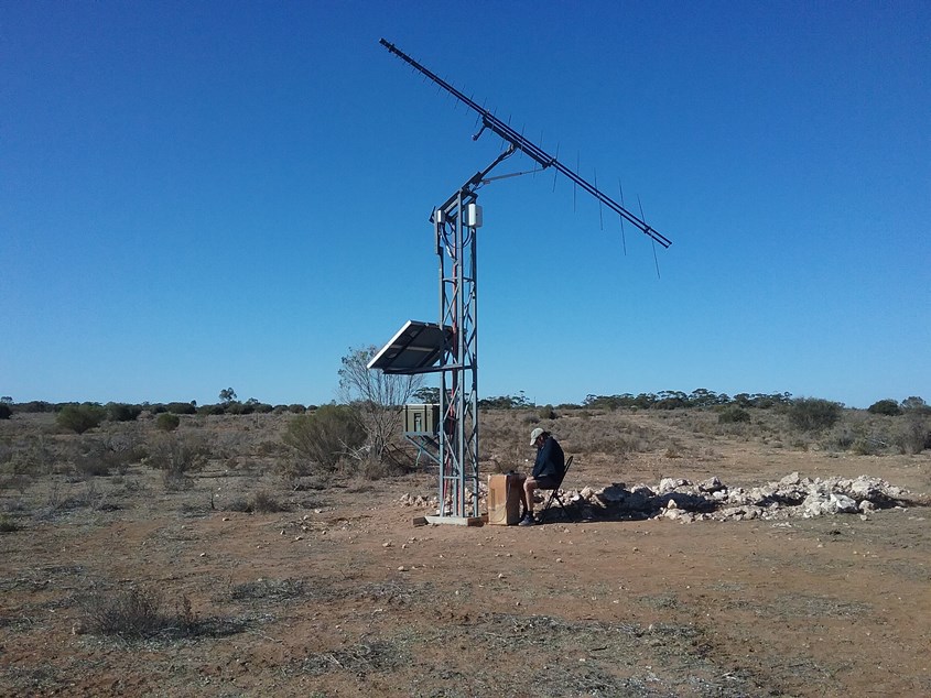
Peter had started work on making a new high frequency (70 to 300 MHz) crossed polarized antenna and once the request to MWA had paid off, he really got going.
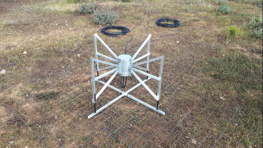
The above picture taken in September 2022 is of the new antenna at the site.
Peter completed the manufacture of the new antenna and started building up the additional receivers we had purchased and eventually installed them and 2 new raspberry Pi's in a nice Stainless Steel box that was donated (thank you Gerard for finding that).
Working bee on the 23rd of March 2023
in Peter's words
"Today's venture out to to our radio site was a significant step forward in the development of the capabilities of the ASSA radio astronomy receiver site. There were a couple of historical technical issues that needed to be addressed and some new ones that needed to be introduced, I am confident that we were able to fulfill both tasks to some success.
The priority for the day was to provide an electrically quiet environment for data communications between the two LWA receivers and their computers. Hopefully this has been achieved with the new computer enclosures, time will tell. If you take a look at the images created today from _62 & _63 once they had been restarted, you will see the difference background RFI created by the container's inverter between 0745UT and 0815UT.
While Blair and I were sorting out the mechanics, soldering and spectrometer support stuff in the container, important things were happening elsewhere.
Of a slightly lesser priority but long overdue, today was also about the initial MWA spectrometer installation. This new capability gives us a better coverage into the VHF region, using the LNA's donated to us by the MWA Project Office and our MWA prototype antenna. I used the word initial because Duncan has some hardware suggestions that should provide some provide significant performance improvements over the current configuration, I also have further changes that should enhance operation. I'm not sure if we captured any, or many images today, but I wouldn't be surprised if we didn't. Everyone, and I mean everyone onsite, was into whatever needed to be done. While we were slogging it out in the Sun, Tigue was preparing a refreshing lunch for everyone.
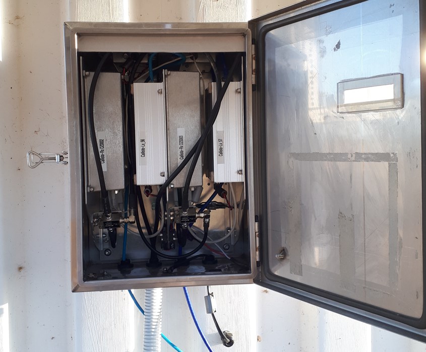
The picture shows the new receiver setup for the MWA antenna which is now secured to the outside of the container at our site.
Squeezed into the box are 2 receivers, 2 raspberry Pi 3B+, 2 power supplies for the rPi's and 2 bias T's to feed power up the coaxes to the MWA low noise amplifiers.
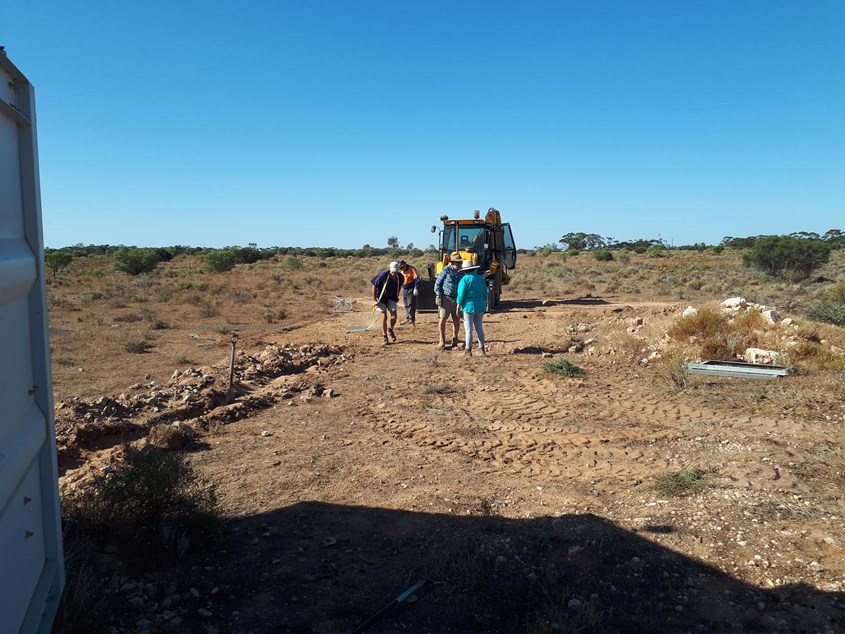
David did the heavy lifting with the JCB to clear the antenna site for an oversize ground plane of galvanized mesh donated by Duncan and I. Beverly and Duncan prepared and laid the conduit enclosed coax. run from the container out to ground plane and connected the MWA antenna. The shallow trench was partially filled using the JCB and shovels using sand infused with limestone particulates to order save the HD (orange) conduit from UV deterioration.
By this time, the day was looking older as the Sun began to sink toward the horizon, perhaps it was just me feeling older. The march flies 'bite' had left a scar one one or two of us and it was time to head elsewhere, or at least home.
When the MWA enclosure was powered up just prior to our departure, only one of the two Pi's powered up correctly. I suspect that the trip up may have caused a problem with the SD card interface which may be easily rectified.
So for the next couple of weeks, Australia-ASSA_datecode_timecode_57.fit should be able to be sent to and images observed from the e-Callisto Observations webpages, along with the _60, _62 & _63 spectrometer images. In the meantime, I'll endeavor to rectify the Australia-ASSA_datecode_timecode_56.fit transfers to the e-Callisto network and resolve the problem. If not, it's a nice drive up to the Murraylands this time of the year."
Peter and I did revisit the site and changed out the faulty rPI and for a few weeks we had all 5 receivers working.
However,
Winter is upon us, and poor solar power harvesting has caught up with us (again) and we have had to turn off the new MWA system until we can upgrade the solar installation on the container.
Hopefully, next week!
8th of May 2021
massive radio outburst, 7th of May, see details at Callisto Data
News Flash (23/4/2021)
First Light on our new low frequency Callisto system see the latest Solar outbursts in Callisto Data
A small group within ASSA (3 of us initially) decided we wanted to be part of the world wide Callisto project and set about building suitable equipment and antennas. We started in 2014 and what follows are highlights of our journey to achieve our outcome with the latest updates first.
We have a radio quiet(ish) site out near Walker Flat alongside the River Murray in South Australia approximately 100 km from Adelaide, a city of more than 1 million people, where we have installed our Callisto receivers.
Currently our site looks like this. 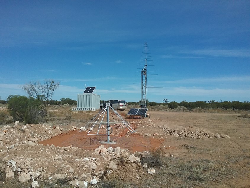
The 'triangular' antenna at the front of the image is our new low frequency crossed polarized 'active' antenna covering the HF band from 5 MHz to about 100 MHz and in the background is our Sun tracking log periodic antenna (LPA) with a working frequency range from 100 MHz to 850 MHz in the VHF / UHF band.
This picture was taken in mid March 2021, a week after our big working bee shows the site as it is with some earthworks still to do.
There are 2 solar arrays, one for the receivers and equipment located at the tower and the other on the container for the computers, communications equipment and an Echopro 24 bit seismic recorder with a Wilmore Mk111 attached to it 15 metres to the east (LHS) of the container as part of Seismological Association's earthquake monitoring system.
The triangular antenna is very similar to those used around the world for large low frequency radio 'telescopes' and while we have and only need one antenna for our solar work, they combine the outputs from hundreds of antennae for what they do. A typical site overseas is the Owens Valley Long Wavelength Array.
Callisto Phase 11 (mid 2020 to 2021)
There is a gap in the frequencies that the 'standard' Callisto receiver can cover at the 'low end' and to get around that lack of coverage, we needed to 'move' the low frequencies higher up to where the receivers do work.
We have put in considerable effort to design and build equipment to allow us to do this.
Peter has been the driver for phase 11.
2 new receivers were purchased from Christian Monstein, we've designed and built new antennae and some RF mixing equipment.
The new crossed polarized active antenna can receive from below 10 MHz to 160 MHz and has about 40db of gain over a vertical whip antenna. We have limited the receivers from 10 Mhz to 88 MHz, as the Earth's atmosphere is not transparent below 10 MHz and the FM band is from 88 MHz to 108 MHz so there is no point in looking at that!
There was a lot to build, we've made everything, done some testing and are now sending data to the host site at ETH in Zurich.
A massive working bee at the beginning of March 2021, with 4 of us, saw the new system physically installed and running.
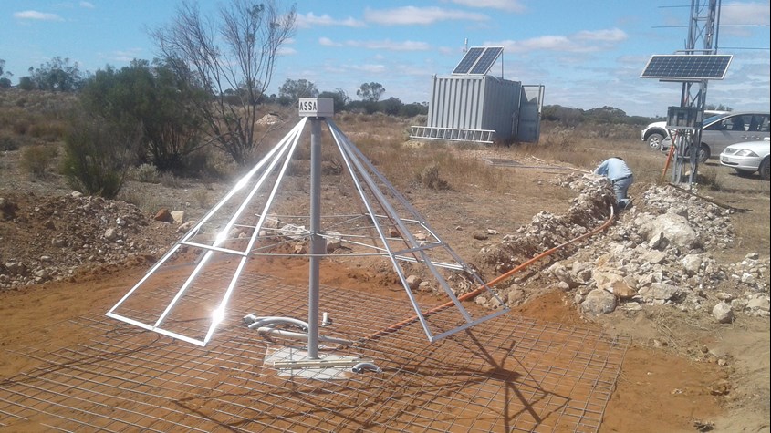
The above picture shows the mesh ground plane and conduit run with David working on the conduit.
Another working bee a week later saw most things finished.
A picture taken late March 2021, shows that David's tidied up the civil works and filled in the trenches somewhat, (it's great to have access to a backhoe!)
We took the solar panel off the tower and have added another 190w panel to a big frame giving us almost 400 watts of battery charging capacity on a sunny day, mainly because the additional 2 receivers, 2 new LNA's and local oscillator draw a lot more energy than before.
With winter and clouds fast approaching, we wanted to make sure we can get enough energy into the battery on cloudy days.
You can see the new solar 'array' at the foot of the tower. Hopefully, the wombats and kangaroos will leave it alone!
Currently (April 10th 2021) , all 3 receivers are working with data being sent to ETH every 15 minutes.
25th March 2021 work bee.
We had discovered that the original battery wasn't up to the new current demands of the new installation, and decided another trip was required rather urgently to replace the battery.
We had a few issues with the computer not being able to handle all the data from the 3 receivers. We were seeing the occasional corrupted files and that prompted the computer and serial communication changes.
We installed a new industrial computer (thank you very much David!) in the container, and changed the way the serial communications from the computer to the receivers out on the tower were being done.
We found some differences between receivers, so we put 2 similar receivers on the new low frequency bow tie antenna (receivers C26 and C86) and have put the original C01 on the VHF / UHF LPA. Peter tidied up the 'up converter' box for the new antenna, changing some attenuation values given the data from the last couple of weeks.
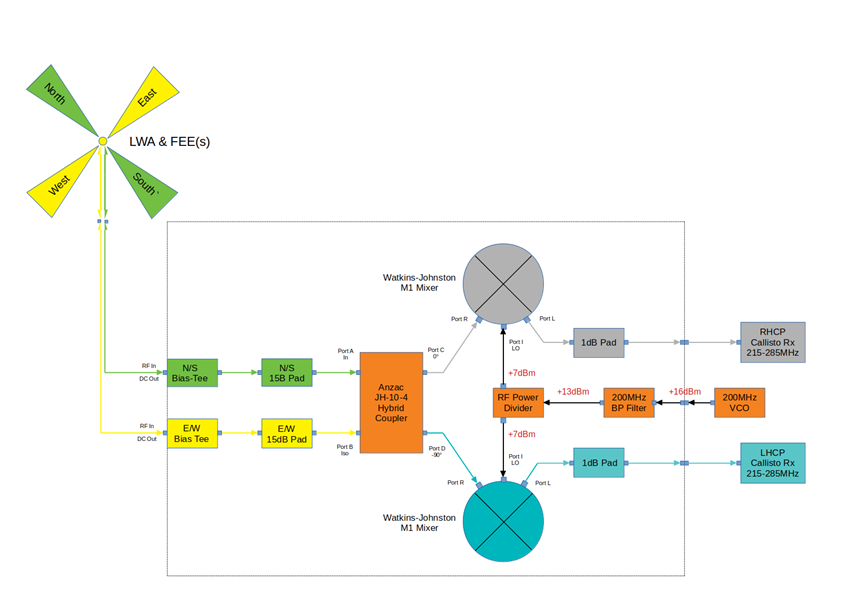
So how does the new Callisto system work?
An up converter 'mixes' a 200 MHz local oscillator signal with the high level signals from the cross polarized antennae FEE's ( 10 MHz to 160 MHz) and produces 2 signals that are from 210 MHz to ~300 MHz), one for each polarization. The receivers then 'tune' from 215 to 287 MHz, missing the 'up converted' local FM band and effectively receiving signals in the range from 15 MHz to 87 MHz. The Callisto software then sorts everything out!
Frequency up converter.
Here's the schematic of the reconfigured up converter (v2).
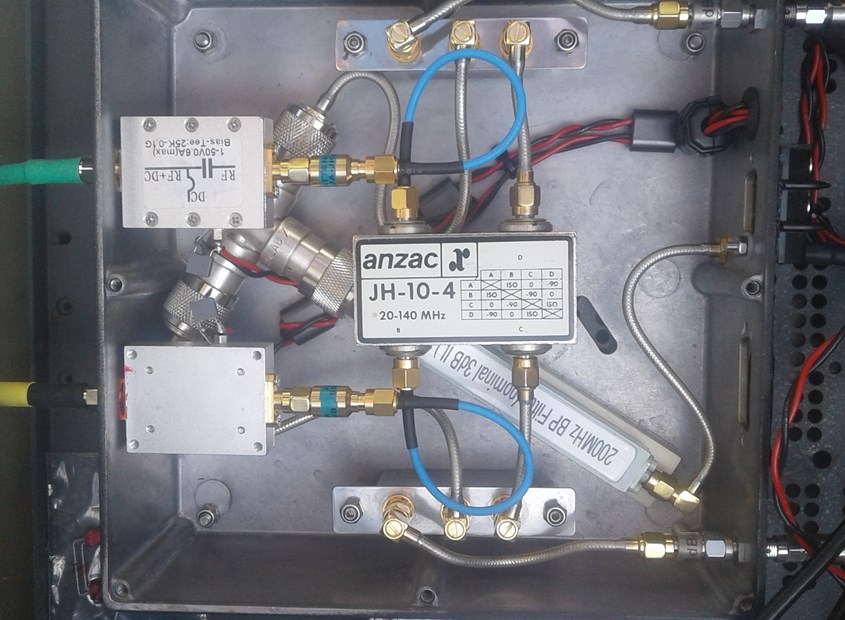
This is what the reconfigured up converter that Peter built looks like.
Inputs (yellow and green) on the far LHS, Bias T's LHS silver boxes, send power up the coax cables to the Front End Electronics (FEE) at the antenna, the 2 mixers top and bottom of the box. The 200 MHz local oscillator designed and built by Duncan is not shown here. (we've spent a lot on gold plated connectors!)
As noted before, the Earths atmosphere isn't transparent to radio signals below about 10 MHz and there is a lot of 'noise' in the FM band of 88 MHz to 108 MHz, so we want to exclude all of that.
The VHF / UHF receiver on the LPA has had it's frequency range changed to exclude everything below about 110 MHz.
Changes to the receiver power supply system.
Receiver battery replacement.
We replaced the battery that powers the receivers with a brand new 100 Ahr AGM lead acid deep cycle battery from Aldi (conveniently on special for $200) as the original one wasn't storing enough energy anymore to get through the night with the increased load despite having almost double the solar charging input available from before. The battery was 6 years old and second hand when it was given to me, so it was well past its use by date of 4 years.
To make sure that we get maximum life out of the new battery, I have made a GPS controlled power switch, that turns the power to the receivers off at night.
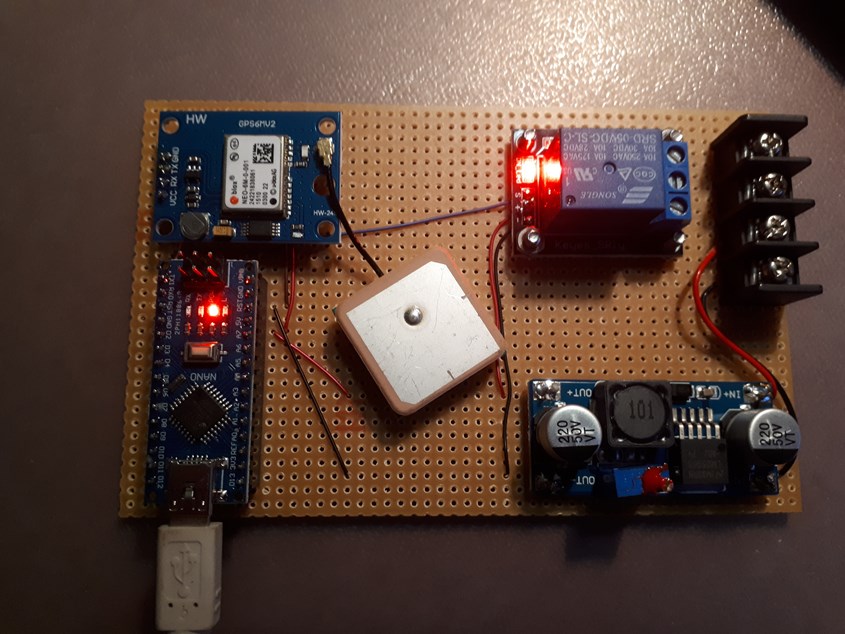
Here's a picture of the GPS driven time switch being tested.
Arduino lower LHS, Ublox NEO 6M GPS upper RHS, GPS antenna is the square silver 'thing' in the middle, 12 volt to 5 volt power supply lower RHS, power relay and power input upper RHS.
All up cost of the parts for the GPS switch was less than $40 from my local Altronics store and a couple of hours at the work bench to make it and write some code.
The operation of the switch is fairly straight forward.
Time is received by the GPS receiver and a data string in Universal Time (UT) is generated and sent to the Arduino. It parses the data string from the GPS, converts the time to 'decimal hours' (so much easier to play in decimal time than hours, minutes and seconds!), does a check to see if we want the power on or off given the current time and then turns the power on or off as required.
From April to September, we only collect data from about 22:00 UT through to 09:45 UT, so we can power down the receivers for 12 hours during the night, conserving considerable amounts of energy during the cloudy winter months.
Callisto Phase 1 (2017 - 2018)
A lot of work went into making the tower, antenna and site preparations, by mid 2018 we had phase 1 VHF / UHF installed and running.
This picture taken around mid 2018 shows Peter checking some settings in the software on the raspberry Pi the nearly completed VHF / UHF Callisto phase 1 installation.
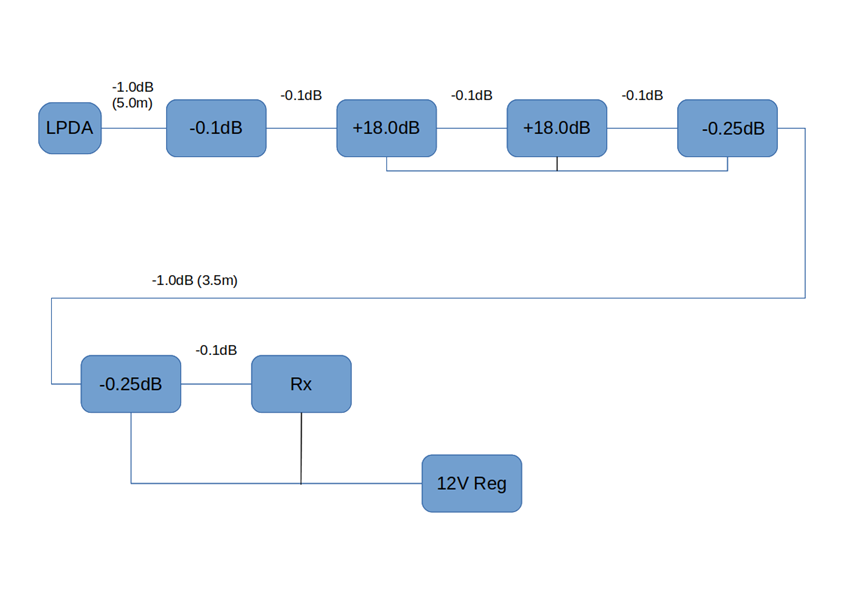
The above schematic is the current (2021) RF gain and loss statement for the VHF / UHF Callisto phase 1 receiver system that uses the Sun tracking log periodic antenna (LPA)
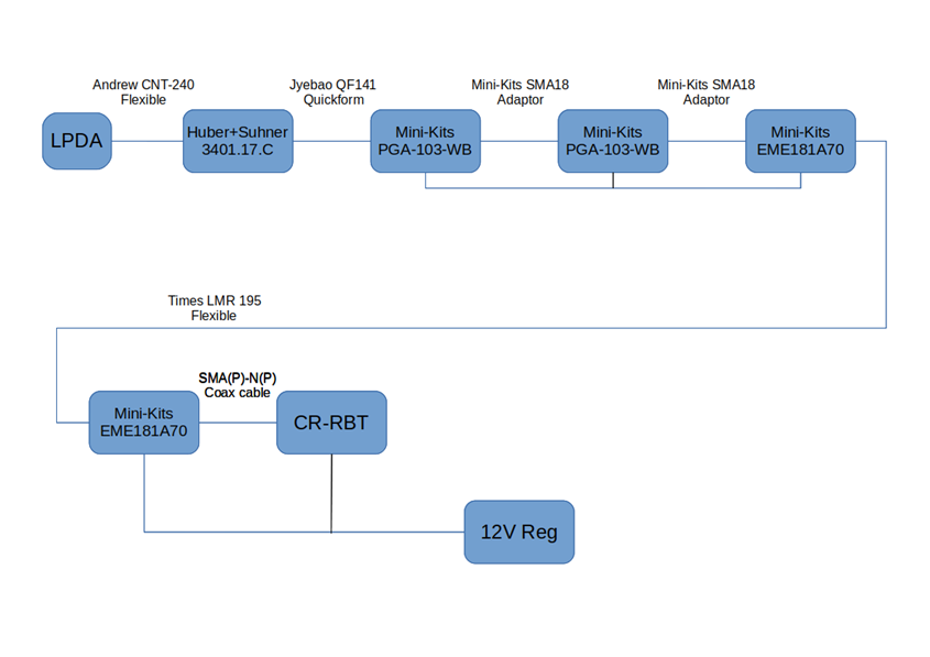
The above schematic is the current (2021) hardware configuration of the Callisto phase 1 VHF / UHF system
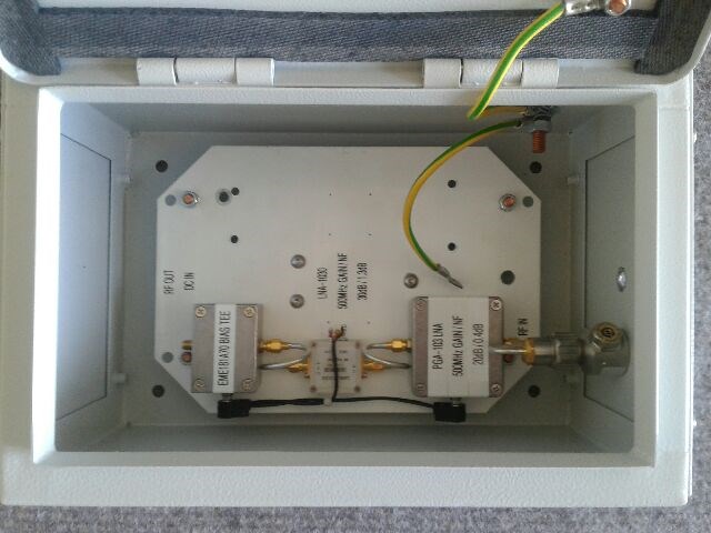
Above, MiniKits EME181 Bias T (LHS), Minikits PGA103 LNA (RHS) and lightning protection (far RHS) in a weather proof box, this goes between the antenna and the receiver (late Jan 2018), slight changes were made and the 2nd LNA in the middle was changed to another PGA103.
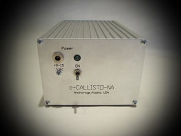
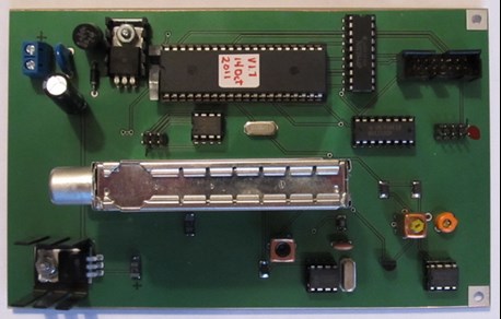
This is what the receiver(s) look like. Clothed on the left and the naked internals on the right, the actual receiver is the long silver thingy.
We have 3 of these, one on the Phase 1 VHF / UHF system and 2 on the Phase 11 HF system.
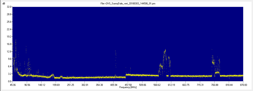
A full receiver 'scan' at our proposed site using a short log periodic antenna in a vertical orientation (March 2018).
The 'stuff' around 95 MHz is the FM band, 560 MHz -620 MHz and 750 MHz -790 MHz are TV station transmissions. The 'step' at 450 MHz is the Receiver changing bands.
We had done similar scans closer to Adelaide as well as south of Adelaide, and decided this site offered the best solution for us as in low(ish) radio interference (RFI), distance to site and on site infrastructure. The site host, David and Tique, offered considerable help to us in setting up this site and we are greatly indebted to them for that.
On behalf of the team (Peter, John and Blair), a very big thank you to our hosts David and Tique. Without your support, this would not of happened!
Read about the Phase 1 installation here.
Some further reading on what we have done as part of the Callisto phase 1 project.
- ASSA Callisto Antenna construction A short story on the log periodic antenna for the Callisto project by peter
- ASSA Callisto front end electronics Discussion about the front end electronics for the Callisto project by peter
- Callisto antenna installation update 16/04/2019 An update on progress at the Receiver site`
We had an LNA (a PGA103 from Minikits) on the log periodic antenna fail, and had a discussion with new team member Duncan about PGA103's. From those discussions, it was suggested that some additional components be added to the input stage of the PGA103 to give the PGA103 LNA's some overload protection and to improve the low frequency stability. That was done and 2 modified LNA's are now in use.
Update Dec 2020
The Sun is waking up (finally) as we move into the next solar cycle, our Callisto installation has been performing way better than we ever thought it could and we have recorded dozens of solar radio bursts. We had the highest number of Solar radio outburst detection's within the Callisto network in December 2020.
Originally a raspberry Pi was used as the computer for Phase 1 but the added requirement for Phase 11 would of required 2 more raspberry Pi's and it made it more sense to use an industrial computer for all 3 receivers. The rPi computer which was out 'on the tower' has been replaced with a proper 12 volt powered, industrial computer installed in the container. This allows us considerably some more flexibility in what we can do at the site in the future. It also introduces some issues as it is a Windows 10 operating system and the ability for us to control when updates are done is very limited. Time will tell if this is a big problem.
Some Callisto related links
Monitoring the Sun, Space Academy ('Solar radio patrol made simple') A really good read on why we need to monitor the Sun, how radio bursts on the Sun occur and some of the methods and equipment used for monitoring the Solar radio noise.
https://player.vimeo.com/video/137913627 A historic 20 minute video about the Sun and monitoring it.
https://avertedimagination.squarespace.com/ A link to Alan Friedman's absolutely stunning solar imagery, it is well worth the time to have a look at his fantastic work done with a Solar Max 90 telescope.
https://en.wikipedia.org/wiki/Solar_radio_emission This wiki has some excellent information on solar radio emissions.