Blair's Radio telescope
Blair, Feb 2018
I want to build one too!
I looked at what Peter did for the Adelaide Hills Radio Telescope and I've looked at some of what others have done and decided to have a go and make one for me.
First things first,
I want to 'see' something so what ever I build has got to produce data that means something. I'm not sure Peter did 'see' anything, he should have , enough sensitivity, noise was low enough, recorded at lot of signals, but did he actually receive anything? I'm not sure.
Secondly,
It is going to be in my front garden as I don't have a back yard so its got do do more than just look at the sky! I've got to be able to move it out of the way and it has to look Ok in the garden.
So,
It has to be portable, it has to move and it has to 'look the part'. My partner loves things with wheels, so wheels it will have, that ticks the 'portable and wheels' box.
It will move, that is it will be able to be driven so that it can look at different parts of the sky.
It will have to have several modes of operation if it is going to have any chance of picking extra terrestrial signals up.
And it will have to be computer controlled, so it can run on its own.
I'll need a dish, a front end (feed horn and LNA), a receiver, some form of detector, a mount for the dish, motor drive, computer and quite a bit of time to make it all.
My mate John at Wurillba has lots of dishes. That is an easy one.
Peter had finished playing around with his Adelaide Hills Radio Telescope and was cleaning up his house for sale, He'll have a feed horn and LNA's he's not using. I'll ask!
Carl's just given me a Winradio 1500 receiver.
I can (probably) build a detector that works.
I've got an old telescope drive and I can write software.
That just about ticks all the boxes...
Haven't told 'she that must be obeyed' about it yet.
I'll tell her once I've started............no point killing the project before I've begun!
Time to get out the pencil and draw up a mount for the dish.
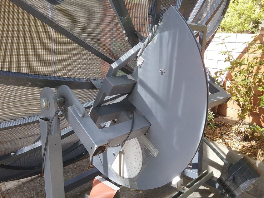
A fairly simple design, it will point North and the dish will be able to be driven up and down allowing all visible angles of declination to be observed. Drift scanning covers all hour angles of right ascension.
An octagonal frame for the base made out of scrap 50 x 50 mm steel tube (I need the welding practice!) , castors on the bottom, a couple of uprights, a 'cradle' for the dish to sit in and we should be right.
A day cutting, grinding and welding steel sees the base, uprights and cradle. (She brings me lunch and asks what I'm doing?) "I'm making a radio telescope" "Oh, I hope it's quieter when it's finished" and walks away....
4 castors, a bunch of assorted nuts and bolts, a couple of sheets of plywood, a roll of Mig welding wire and some grey spray paint from Bunnings.
A trip to John's for a 4 foot dish and 2 days working out how to drive the dish.
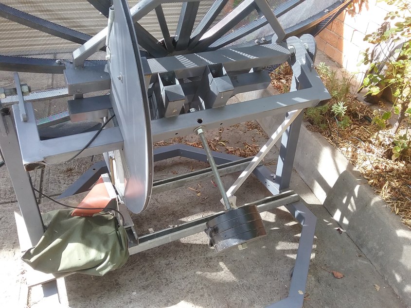
Toothed belts and pulleys are wonderful things, much easier to work with than worm drives, so I ordered 2 metres of belt and some pulleys from ebay for the vertical drive. Next I need a large 'drive pulley' for the Dec axis. A sheet of 8 mm ply with a 3/4 of a large circle drawn on it, cut with a jigsaw and sanded followed by 2 x 3 mm sheets of ply either side makes the large 'pulley'.
The Dish Mk 1
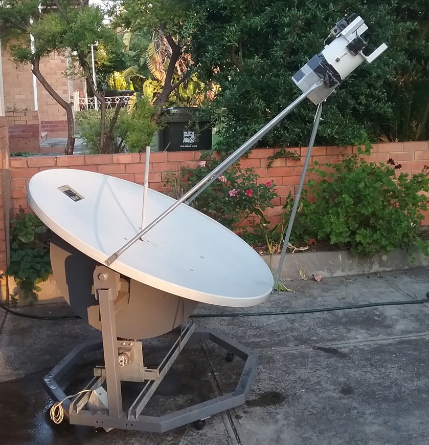
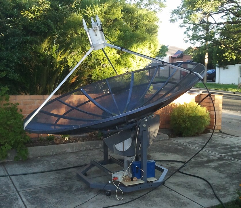
The 'finished' radio telescope with a 4 foot 'offset focus' solid dish from John and using Peter's feed horn and one of his very expensive Low Noise Amplifiers (LNA's).
You can see the stepper motor and RS gear box towards to base of the 'scope' on the aluminium plate.
"It looks OK, where are you going to put it?", "In the garden", "Well the birds might like it if it fills up with water when it rains". Was that a thumbs up?
The piece of white conduit pointing straight up is a highly accurate 'sun' finder, you move the dish around until the shadow from the sun is at minimum. It is adjusted by trial and error, but once lined up is quite accurate.
The octagonal base is about 1.2m across. Total weight is about 100kg, cost .. lets not go there but parts and petrol probably came to about $200.
The Drive System
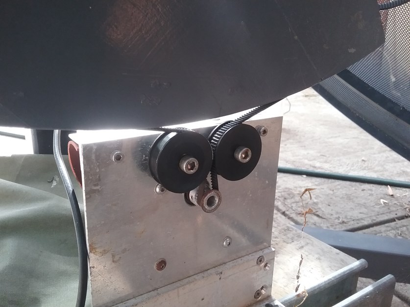
The 'other side' of the motor and gear box showing the toothed drive pulley, belt and Delrin idler rollers.
There was a bit of fiddling around to get the large dish drive pulley lined up, but the run out is now less than 1 mm.
The motor drive is an old 1.2 degree stepper motor and an RS Components 50:1 gearbox with a small 14 tooth pulley on it. Drive electronics is a pic micro stepper controller that I'd built for a telescope mount years ago. Toothed pulley and belt purchased off eBay for about $10.
The Detector and Integrator
I built a 'copy' of the original NRO square law detector using a germanium diode and an RC integrator with a 16 bit analogue to digital converter (ADC), and while it worked, I figured I could do better.
A few years ago, I had rebuilt an SSP3 photometer for the ASSA variable star group and had added a serial digital output to it. I thought I could integrate some of that design into this.
I tried a few things and settled on a precision rectifier followed by a high linearity voltage to frequency converter with a MicroChip 'pic' micro doing the counting. Photometers typically use voltage to frequency converters as part of their integrator, and if it's good enough for optical, then it might work for radio!
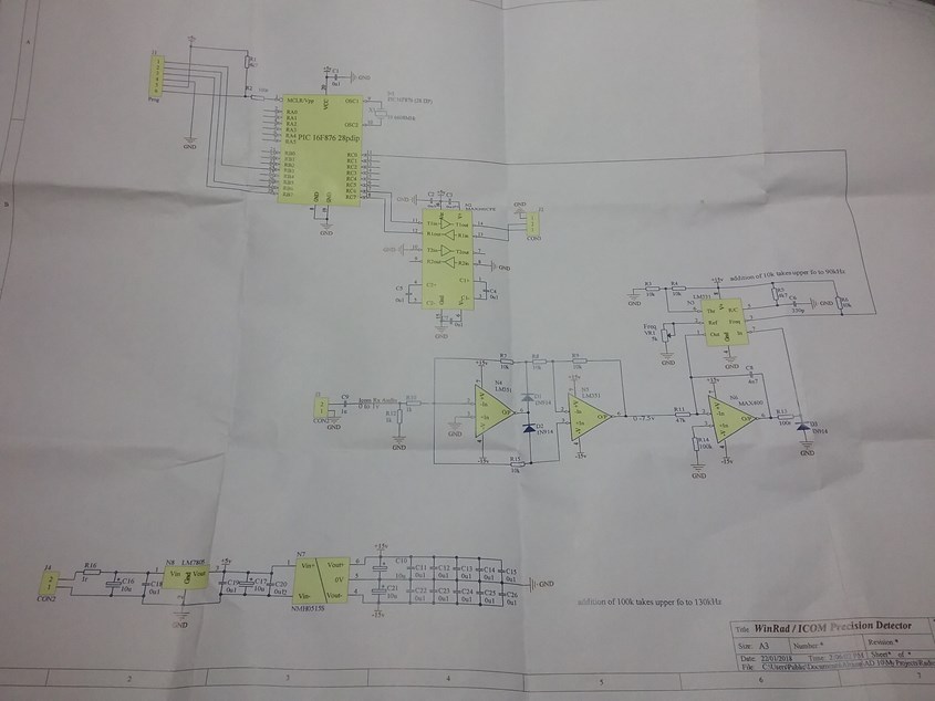
The new hi precision integrating detector.
Circuit description, The AC out put (audio hiss) from the radio is rectified (turned to a varying DC level by 2 op amps and 2 diodes). This varying DC level is then used to control a highly linear voltage to frequency converter, the frequency (pulses) are then counted by the PIC micro for a period of time (10milli Seconds to 65 Seconds) and then the number of 'pulses counted' is sent to the main computer where it is recorded into a data file along with the scopes' elevation, local sidereal time, a UT date and time stamp, the receiver's frequency and integration period.
As I'm counting pulses output from the voltage to frequency converter, there really is no limit on how 'big' the count can be and effectively, I have a 24+ bit digitizer on my radio telescope.
This method (counting pulses over time) also smooths out any rapid variations (scintillation) in the signal and very effectively 'averages' the signal over time.
Counting for longer time periods reduces the 'noise' in the signal, however, it of course takes longer to capture data.
The detector was tested on the work bench with a precision voltage source and achieves a linearity of better than 0.01%. This means that if you double the signal level you do actually get double the number of counts. This might seem trivial and what you would expect but its quite hard to do in practice without spending a lot of money.
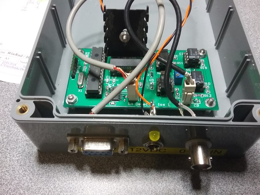
The finished detector.
A small printed circuit board (45mm x 90mm) with 7 integrated circuits on it. The long integrated circuit on the LHS is the PIC micro that does the counting and communicating to the main computer. The parts on the RHS do the rectifying and voltage to frequency conversion.
A couple of weeks writing software at night time and it's all sort of running.
The receiver could change frequencies if required, the dish can move in elevation if required and the integration period can be changed if required.
Is it working? Well yes, if I point it at the sun it gets a massive signal, I can adjust the position of the feed horn (focusing) to maximize the received signal while pointing at the sun and watching the received signal strength.
But, do I 'see' anything else?
Setting the receiver's frequency to 1420.4058 MHz, the rest frequency of hydrogen and the dish to scan up and down while collecting data every second for a whole day (covering about 1/4 the visible sky from where I live) doesn't produce much, a few spots of 'noise', a few lines that could be local interference and a big blob when the sun is seen is about it.
Ok, lets make the receiver automatically change it's frequency a little after each 'integration' (a bit of a software rewrite over a couple of nights), and keep the dish in one place and 'drift scan' for a day.
The receiver can now be set to almost any frequency, so lets go 1420.4 MHz +- 100 kHz with 1 second integrations.
Looking at the computer screen the next evening, there is a 'hint' of a signal as the dish looks at the Sagittarius region (the centre of the Galaxy) at frequencies that are not at the rest frequency of Hydrogen. This is exciting times.
A few more scans with bigger changes in frequencies and we just start to make out a signal, that is in the same place on the screen each day.
Going to need a bigger dish! (start of onset of Aperture Fever)
'Hi Greg, you said some time ago that you had a 2.3 m dish, can I borrow it?" "Yep" , "I'll be around shortly"
The Dish Mk 11
Some more welding and here we are!
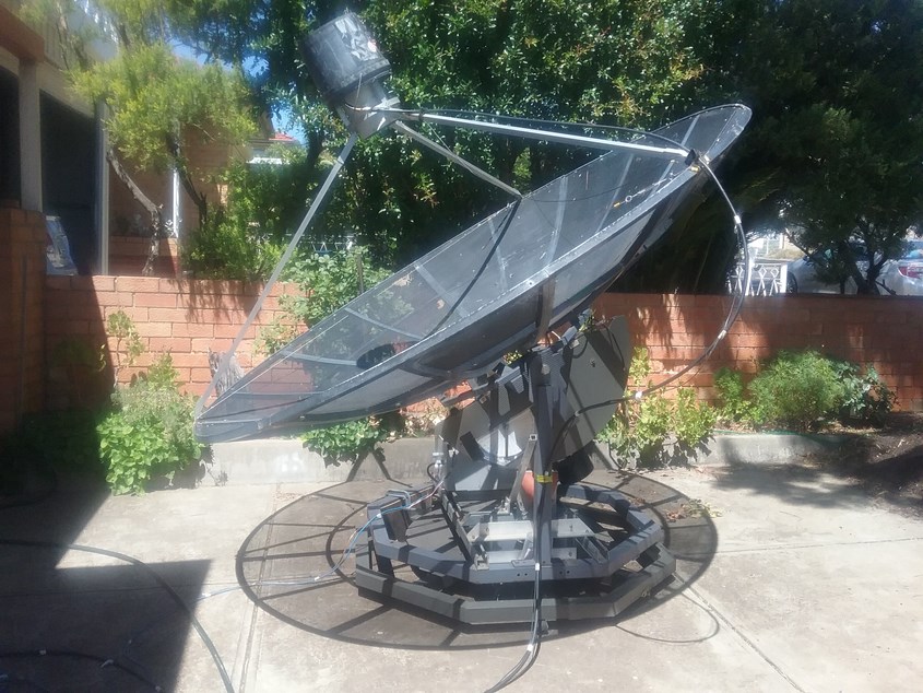
The Mk11 dish during an observation session
Note the Skywatcher counter weights and the weather proofing for the electronics and stepper drive motor.
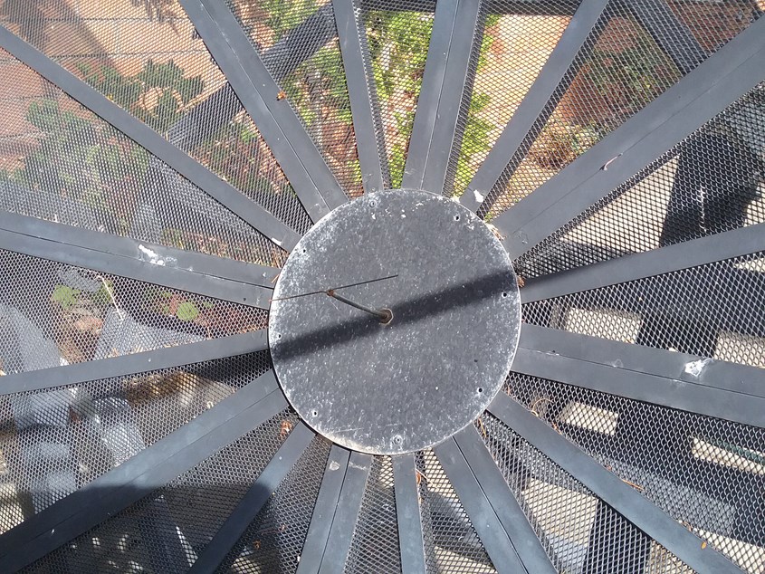
The little antenna at the middle of the dish is used to provide a 'calibration signal' from a noise generator which gets turned on by the drive system for the first sample of every scan.
The hope is that the calibration signal will be constant and can be used to measure the LNA / receiver's gain which probably changes with temperature and thus compensate for changing system sensitivities due to temperature changes.
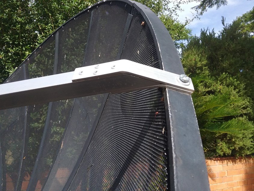
The supports for the feed horn were made from 20mm square Aluminium tube with brackets cut and bent to shape.
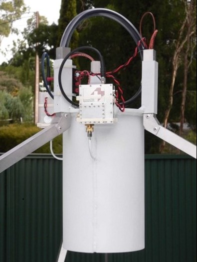
Peter's original nice new feed horn assembly and LNA's.
Now Peter has 2 very expensive LNA's, however, they were not water proof and the whole assembly suffered considerably during the 4 years it was on his RT.
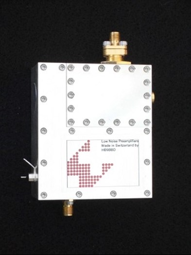
One of the LNA's had got water inside it and no longer worked.
I pulled it apart, lots of corrosion and some dead parts, I cleaned it all up, replaced the dead fet bias supply and put it on the spectrum analyser, it tuned up a treat despite the corrosion
It needs a coat of paint, but I'll put a bucket on it for now to keep the water out and tidy it up later
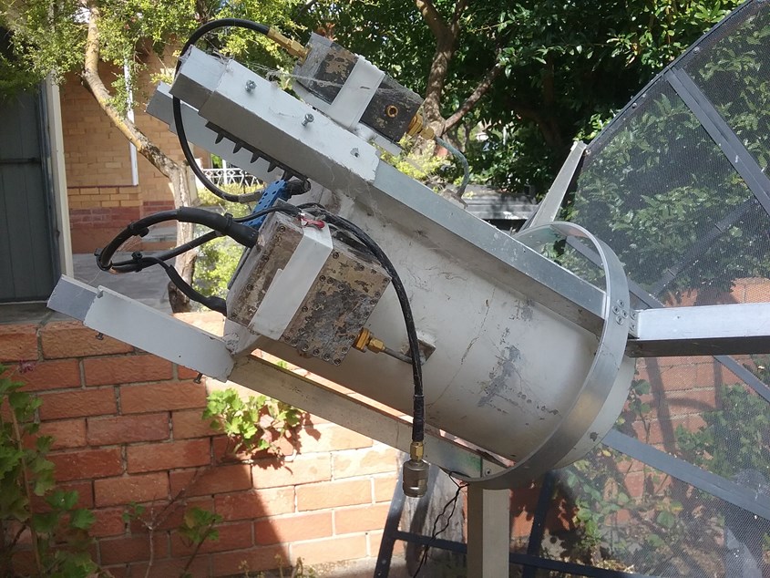
The upgrade to the bigger dish and Peter's LNA was a LOT of work!
Now I had 2 LNA's and at least 4 times the surface area. (aperture fever?)
Lets see what we get this time.
The dish can move in elevation (up and down) and the receiver can change frequency, so over a day I can either scan a lot of sky at a given frequency or I can scan a thin strip of sky at a lot of frequencies.
After a bit of trying out settings and more changes to software, I decided that the thin strip drift scan with a lot of frequencies would probably yield the best collection practice.
A few nights later I got this.
Almost a full day's scan of a thin 5 degree wide strip at Declination of -5 degrees of the sky at a Doppler shift of up to +- 106 km / second
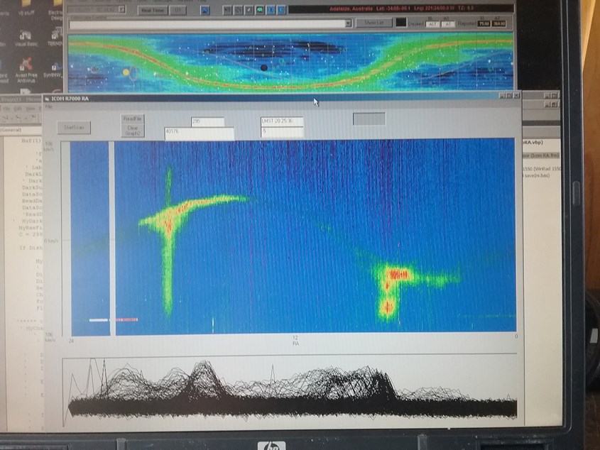
Screen shot of the first signals I received (hotter 'red' colours are stronger signals)
Top of screen is Radio Eyes from Sky Publishing.
LHS green / yellow / red Aquilla region, RHS Orion region.
In the middle of the display is the 'rest frequency of hydrogen', very little signal except near the Sagittarius arm of the Milky Way .
Top of the graph is higher in frequency and coming towards us and is 'blue' shifted,.
Bottom of coloured graph is lower in frequency and travelling away from us and is therefore is red shifted.
There was a reason I didn't 'see' anything before.... there was nothing to see! (at the sensitivity of my original dish).
Where to from here,
Tune up the software and electronics, some minor hardware changes, put the dish on the roof of the shed so it can 'see' more of the sky and start gathering data.
Once that is done, more software to analyse the data and turn it into some maps of the sky.
For now, I'm just happy that I can 'see' stuff.
Further reading on a similar sized Radio Telescope and data collected by Dr. David Morgan in the UK is here.
UPDATE Dec 2020
It has been a while, and I've been busy modifying the mount to have dual axis drive.
The Dish Mk 111
Note the additional larger base piece added to the bottom of the existing mount, it has a trailer stub axle as the centre bearing and another stepper motor / gearbox to drive it.
The mount can now track across the sky and stay pointed for many hours. I can even add an optical 'guidescope' and 'lock onto ' an object. The 'drive' control electronics is based around an Arduino DUE single board computer with stepper motor drives. A lot of code has been written that now makes the telescope a 'stand alone entity', I can for example give the scope RA and DEC coordinates and the telescope will go and point to the location and follow it for hours.
The original LNA's from peter have suffered considerably, and while they still 'work' their performance leaves lots to be desired. They are now quite noisy, caused by the corrosion changing the input coupling and affecting the noise performance. New member Duncan has set me a task to design and build some new LNA's.
I will write up all the changes made to the drive system, put all the code in a file some time soon and put it on the site.